Figure 3.2: SampleWaveLine scene
This year, I participated in a hackathon called Art Hack Day 2018 * 1 where I personally created a visual work using Unity.
Figure 3.1: Visual part of Already There
In my work, I used the technique of drawing a wireframe polygon using the Geometry Shader. In this chapter, we will explain the method. The sample in this chapter is "Geometry Wireframe" from https://github.com/IndieVisualLab/UnityGraphicsProgramming2 .
[*1] Art Hack Day 2018 http://arthackday.jp/
I think that LineRenderer and GL are often used to draw lines in Unity, but this time I will use Graphics.DrawProcedural assuming that the amount of drawing will increase later.
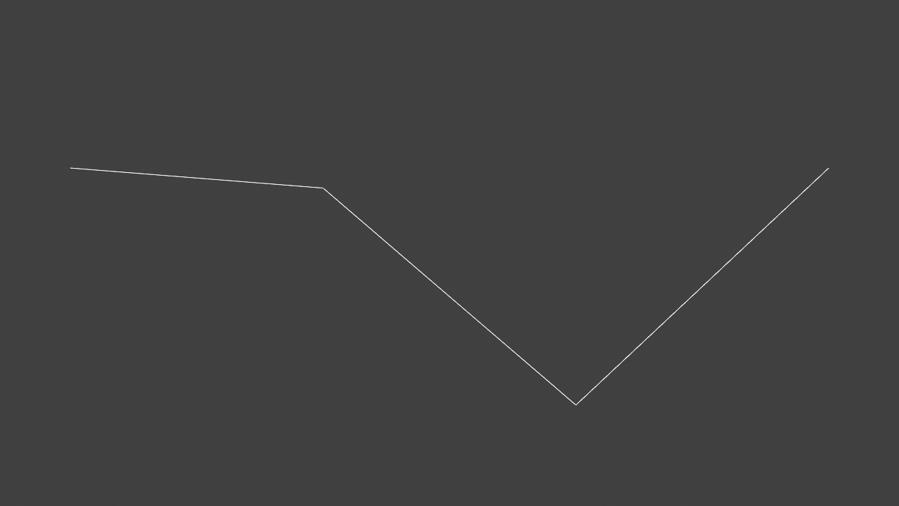
First of all, let's draw a simple sine wave. Take a look at the sample SampleWaveLine scene .
Figure 3.2: SampleWaveLine scene
For now, press the play button and run it, and you should see an orange sine wave in the Game view. Select the WabeLine object in the Hierarchy window and move the Vertex Num slider on the RenderWaveLine component in the Inspector window to change the smoothness of the sine wave. The implementation of the RenderWaveLine class looks like this:
Listing 3.1: RenderWaveLine.cs
using UnityEngine;

[ExecuteInEditMode]
public class RenderWaveLine : MonoBehaviour {
    [Range(2,50)]
    public int vertexNum = 4;

    public Material material;

    private void OnRenderObject ()
    {
        material.SetInt("_VertexNum", vertexNum - 1);
        material.SetPass(0);
        Graphics.DrawProcedural(MeshTopology.LineStrip, vertexNum);
    }
}
Graphics.DrawProcedural runs immediately after the call, so it must be called inside the OnRenderObject. OnRenderObject is called after all cameras have rendered the scene. The first argument of Graphics.DrawProcedural is MeshTopology . MeshTopology is a specification of how to configure the mesh. There are six configurations that can be specified: Triangles (triangle polygon), Quads (square polygon), Lines (line connecting two points), LineStrip (connecting all points continuously), and Points (independent points). The second argument is the number of vertices .
This time, I want to place the vertices on the line of the sine wave and connect the lines, so I use MeshTopology.LineStrip . The second argument, vertexNum, specifies the number of vertices used to draw the sine wave. As you may have noticed here, I haven't passed an array of vertex coordinates to Shader anywhere. The vertex coordinates are calculated in the following Shader Vertex Shader (vertex shader). Next is WaveLine.shader.
Listing 3.2: WaveLine.shader
Shader "Custom/WaveLine"
{
  Properties
  {
    _Color ("Color", Color) = (1,1,1,1)
    _ScaleX ("Scale X", Float) = 1
    _ScaleY ("Scale Y", Float) = 1
    _Speed ("Speed",Float) = 1
  }
  SubShader
  {
    Tags { "RenderType"="Opaque" }
    LOD 100

    Pass
    {
      CGPROGRAM
      #pragma vertex vert
      #pragma fragment frag
      #pragma target 3.5

      #include "UnityCG.cginc"

      #define PI  3.14159265359

      struct v2f
      {
        float4 vertex : SV_POSITION;
      };

      float4 _Color;
      int _VertexNum;
      float _ScaleX;
      float _ScaleY;
      float _Speed;

      v2f vert (uint id : SV_VertexID)
      {
        float div = (float)id / _VertexNum;
        float4 pos = float4((div - 0.5) * _ScaleX,
          sin(div * 2 * PI + _Time.y * _Speed) * _ScaleY, 0, 1);

        v2f o;
        o.vertex = UnityObjectToClipPos(pos);
        return o;
      }

      fixed4 frag (v2f i) : SV_Target
      {
        return _Color;
      }
      ENDCG
    }
  }
}
SV_VertexID (vertex ID) is passed to the argument of the Vertex Shader function vert. The vertex ID is a serial number unique to the vertex. Feeling that if you pass the number of vertices to be used as the second argument of Graphics.DrawProcedural, Vertex Shader will be called for the number of vertices, and the vertex ID of the argument will be a value from 0 to -1. is.
In Vertex Shader, the ratio from 0 to 1 is calculated by dividing the vertex ID by the number of vertices. The vertex coordinates (pos) are calculated based on the calculated ratio. The coordinates on the sine wave are obtained by giving the ratio obtained earlier in the calculation of the Y coordinate to the sin function. By adding _Time.y, we also animate the change in height as time progresses. Since the vertex coordinates are calculated in Vertex Shader, there is no need to pass the vertex coordinates from the C # side. Then, UnityObjectToClipPos is passing the coordinates converted from the object space to the clip space of the camera to the Fragment Shader.
Next, let's draw a polygon. To draw a polygon, you need vertices for each corner. It can be done by connecting vertices and closing as in the previous section, but this time I will draw a polygon from one vertex using Geometry Shader. For details on Geometry Shader, refer to "Chapter 6 Growing Grass with Geometry Shader" in UnityGraphicsProgramming vol.1 * 2 . Roughly speaking, the Geometry Shader is a shader that can increase the number of vertices, located between the Vertex Shader and the Fragment Shader.
Take a look at the sample SamplePolygonLine scene .
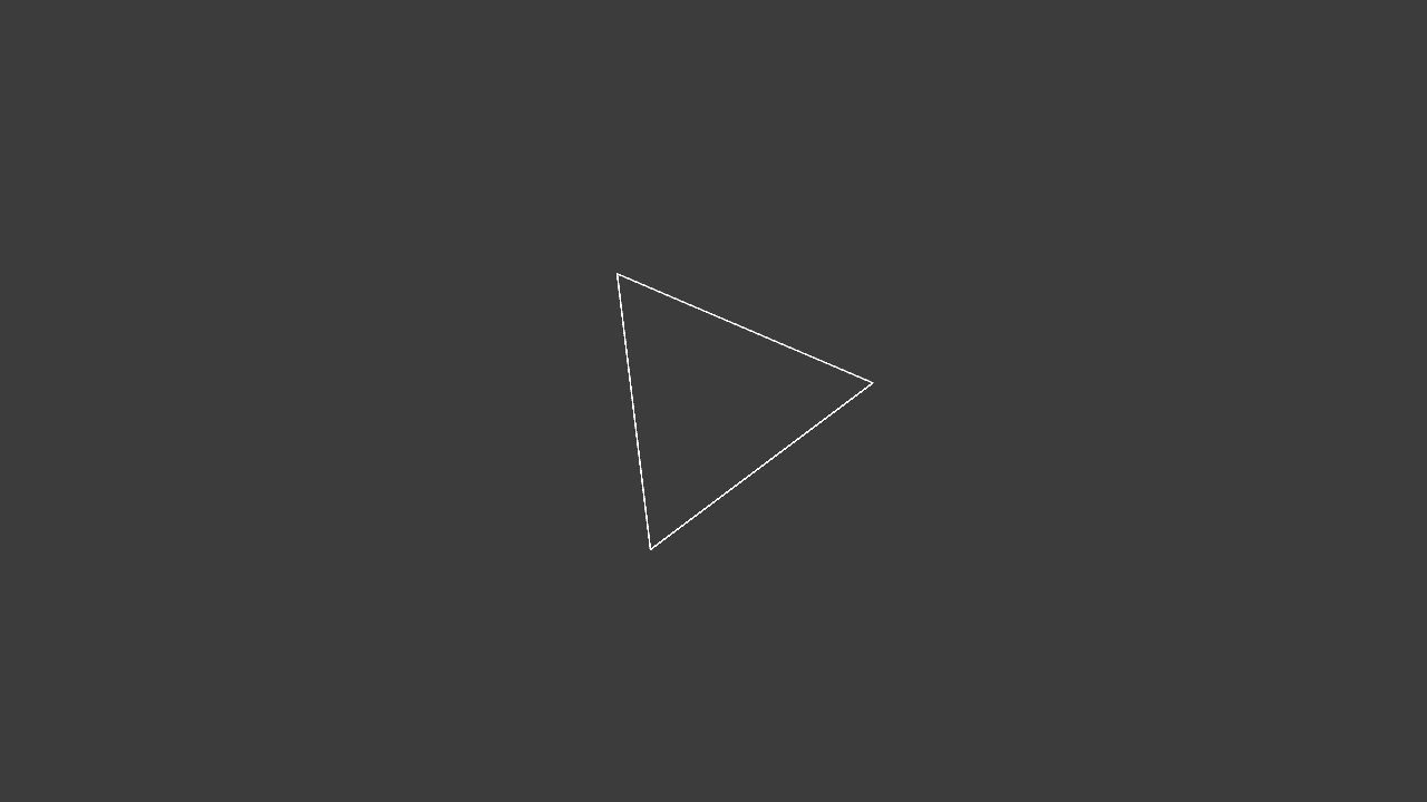
Figure 3.3: SamplePolygonLine scene
When you press the play button and run it, the triangle should rotate in the Game view. You can increase or decrease the number of triangle angles by selecting the PolygonLine object in the Hierarchy window and moving the Vertex Num slider on the SinglePolygon2D component in the Inspector window. The implementation of the SimglePolygon2D class looks like this:
Listing 3.3: SinglePolygon2D.cs
  using UnityEngine;

[ExecuteInEditMode]
public class SinglePolygon2D : MonoBehaviour {

    [Range(2, 64)]
    public int vertexNum = 3;

    public Material material;

    private void OnRenderObject ()
    {
        material.SetInt("_VertexNum", vertexNum);
        material.SetMatrix("_TRS", transform.localToWorldMatrix);
        material.SetPass(0);
        Graphics.DrawProcedural(MeshTopology.Points, 1);
    }
}
It has almost the same implementation as the RenderWaveLine class.
There are two major differences. The first is that the first argument of Graphics.DrawProcedural is changed from MeshTopology.LineStrip to MeshTopology.Points . The other is that the second argument of Graphics.DrawProcedural is fixed at 1 . In the RenderWaveLine class in the previous section, MeshTopology.LineStrip was specified because the lines were drawn by connecting the vertices, but this time I want to pass only one vertex and draw a polygon, so MeshTopology.PointsIs specified. This is because the minimum number of vertices required for drawing changes depending on the MeshTopology specification, and if it is less than that, nothing is drawn. MeshTopology.Lines and MeshTopology.LineStrip are 2 because they are lines, MeshTopology.Triangles are 3 because they are triangles, and MeshTopology.Points are 1 because they are points. By the way, in the part of material.SetMatrix ("_TRS", transform.localToWorldMatrix) ;, the matrix converted from the local coordinate system of the GameObject to which the SinglePolygon2D component is assigned to the world coordinate system is passed to the shader. By multiplying this by the vertex coordinates in the shader, the transform of the GameObject, that is, the coordinates (position), orientation (rotation), and size (scale) will be reflected in the drawn figure.
Next, let's take a look at the implementation of SinglePolygonLine.Shader.
Listing 3.4: SinglePolygonLine.shader
Shader "Custom/Single Polygon Line"
{
  Properties
  {
    _Color ("Color", Color) = (1,1,1,1)
    _Scale ("Scale", Float) = 1
    _Speed ("Speed",Float) = 1
  }
  SubShader
  {
    Tags { "RenderType"="Opaque" }
    LOD 100

    Pass
    {
      CGPROGRAM
      #pragma vertex vert
      #pragma geometry geom // Declaration of Geometry Shader
      #pragma fragment frag
      #pragma target 4.0

      #include "UnityCG.cginc"

      #define PI  3.14159265359

      // Output structure
      struct Output
      {
        float4 pos : SV_POSITION;
      };

      float4 _Color;
      int _VertexNum;
      float _Scale;
      float _Speed;
      float4x4 _TRS;

      Output vert (uint id : SV_VertexID)
      {
        Output o;
        o.pos = mul (_TRS, float4 (0, 0, 0, 1));
        return o;
      }

      // Geometry shader
      [maxvertexcount(65)]
      void geom(point Output input[1], inout LineStream<Output> outStream)
      {
        Output o;
        float rad = 2.0 * PI / (float)_VertexNum;
        float time = _Time.y * _Speed;

        float4 pos;

        for (int i = 0; i <= _VertexNum; i++) {
          pos.x = cos(i * rad + time) * _Scale;
          pos.y = sin (i * rad + time) * _Scale;
          pos.z = 0;
          pos.w = 1;
          o.pos = UnityObjectToClipPos (pos);

          outStream.Append(o);
        }
        outStream.RestartStrip();
      }

      fixed4 frag (Output i) : SV_Target
      {
        return _Color;
      }
      ENDCG
    }
  }
}
A new #pragma geometry geom declaration has been added between the #pragma vertex vert and the #pragma fragment frag . This means declaring a Geometry Shader function named geom. Vertex Shader's vert sets the coordinates of the vertices to the origin (0,0,0,1) for the time being, and multiplies it by the _TRS matrix (the matrix that converts from the local coordinate system to the world coordinate system) passed from C #. It has become like. The coordinates of each vertex of the polygon are calculated in the following Geometry Shader.
Definition of Geometry Shader
  // Geometry shader
  [maxvertexcount(65)]
  void geom(point Output input[1], inout LineStream<Output> outStream)
The maximum number of vertices output from the Geometry Shader. This time, VertexNum of the SinglePolygonLine class is used to increase the number to 64 vertices, but since a line connecting the 64th vertex to the 0th vertex is required, 65 is specified.
Represents the input information from Vertex Shader. point is a primitive type and means that one vertex is received, Output is a structure name, and input [1] is an array of length 1. Since only one vertex is used this time, I specified point and input [1], but when I want to mess with the vertices of a triangular polygon such as a mesh, I use triangle and input [3].
Represents the output information from the Geometry Shader. LineStream <Output> means to output the line of the Output structure. There are also PointStream and TriangleStream. Next is the explanation inside the function.
Implementation in function
Output o;
float rad = 2.0 * PI / (float)_VertexNum;
float time = _Time.y * _Speed;

float4 pos;

for (int i = 0; i <= _VertexNum; i++) {
  pos.x = cos(i * rad + time) * _Scale;
  pos.y = sin (i * rad + time) * _Scale;
  pos.z = 0;
  pos.w = 1;
  o.pos = UnityObjectToClipPos (pos);

  outStream.Append(o);
}

outStream.RestartStrip();
In order to calculate the coordinates of each vertex of the polygon, 2π (360 degrees) is divided by the number of vertices to obtain the angle of one corner. The vertex coordinates are calculated using trigonometric functions (sin, cos) in the loop. Output the calculated coordinates as vertices with outStream.Append (o). After looping as many times as _VertexNum to output the vertices, outStream.RestartStrip () ends the current strip and starts the next strip. As long as you add it with Append (), the lines will be connected as LineStream. Execute RestartStrip () to end the current line once. The next time Append () is called, it will not connect to the previous line and a new line will start.
[* 2] UnityGraphicsProgramming vol.1 https://indievisuallab.stores.jp/items/59edf11ac8f22c0152002588
A regular octahedron is a polyhedron composed of eight equilateral triangles , as shown in Fig. 3.4 . Octahedron Sphere is a sphere created by dividing the three vertices of an equilateral triangle that make up a regular octahedron by spherical linear interpolation * 3 . Whereas normal linear interpolation interpolates so that two points are connected by a straight line, spherical linear interpolation interpolates so that two points pass on a spherical surface as shown in Fig. 3.5 .
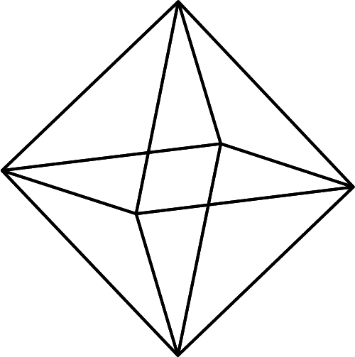
Figure 3.4: Octahedron
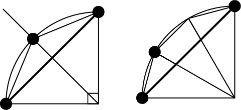
Figure 3.5: Octahedron
Take a look at the Sample Octahedron Sample scene .
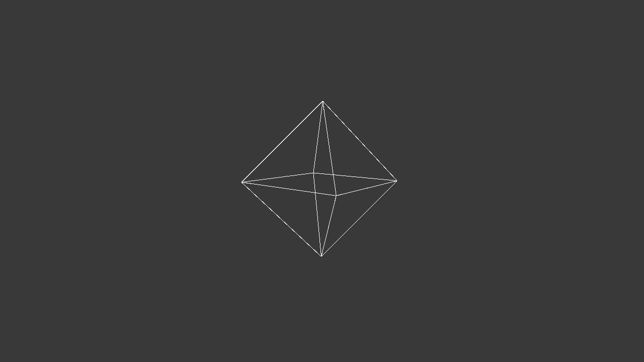
Figure 3.6: SampleWaveLine scene
When you press the run button, you should see a slowly rotating octahedron in the center of the Game view. Also, if you change the Level slider of the Geometry Octahedron Sphere component of the Single Octahedron Sphere object in the Hierarchy window, the sides of the octahedron will be split and gradually approach the sphere.
[* 3] spherical linear interpolation, slerp for short
Next, let's take a look at the implementation. The implementation on the C # side is almost the same as SinplePolygon2D.cs in the previous section, so it will be omitted. OctahedronSphere.shader has a long source, so I will explain only in Geometry Shader.
Listing 3.5: The beginning of the Gometry Shader in OctahedronSphere.shader
// Geometry shader
  float4 init_vectors[24];
  // 0 : the triangle vertical to (1,1,1)
  init_vectors[0] = float4(0, 1, 0, 0);
  init_vectors[1] = float4(0, 0, 1, 0);
  init_vectors[2] = float4(1, 0, 0, 0);
  // 1 : to (1,-1,1)
  init_vectors[3] = float4(0, -1, 0, 0);
  init_vectors[4] = float4(1, 0, 0, 0);
  init_vectors[5] = float4(0, 0, 1, 0);
  // 2 : to (-1,1,1)
  init_vectors[6] = float4(0, 1, 0, 0);
  init_vectors[7] = float4(-1, 0, 0, 0);
  init_vectors[8] = float4(0, 0, 1, 0);
  // 3 : to (-1,-1,1)
  init_vectors[9] = float4(0, -1, 0, 0);
  init_vectors[10] = float4(0, 0, 1, 0);
  init_vectors[11] = float4(-1, 0, 0, 0);
  // 4 : to (1,1,-1)
  init_vectors[12] = float4(0, 1, 0, 0);
  init_vectors[13] = float4(1, 0, 0, 0);
  init_vectors[14] = float4(0, 0, -1, 0);
  // 5 : to (-1,1,-1)
  init_vectors[15] = float4(0, 1, 0, 0);
  init_vectors[16] = float4(0, 0, -1, 0);
  init_vectors[17] = float4(-1, 0, 0, 0);
  // 6 : to (-1,-1,-1)
  init_vectors[18] = float4(0, -1, 0, 0);
  init_vectors[19] = float4(-1, 0, 0, 0);
  init_vectors[20] = float4(0, 0, -1, 0);
  // 7 : to (1,-1,-1)
  init_vectors[21] = float4(0, -1, 0, 0);
  init_vectors[22] = float4(0, 0, -1, 0);
  init_vectors[23] = float4(1, 0, 0, 0);
First, as shown in Fig. 3.7 , we define a "normalized" octahedron triangular system that is the initial value.
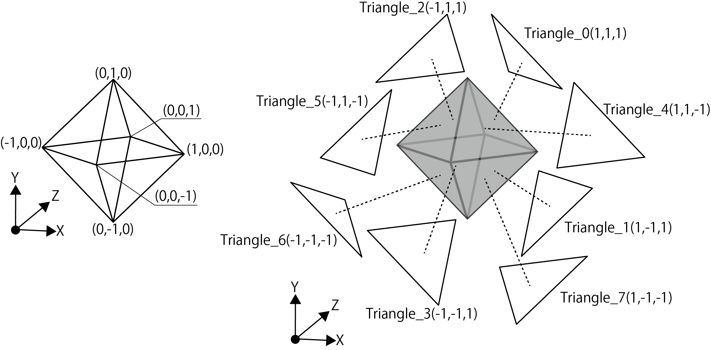
Figure 3.7: Octahedron vertex coordinates and triangles
It is defined in float4 because it is defined as a quaternion.
Listing 3.6: OctahedronSphere.shader Triangle Spherical Linear Interpolation Split Processing Part
for (int i = 0; i < 24; i += 3)
{
  for (int p = 0; p < n; p++)
  {
    // edge index 1
    float4 edge_p1 = qslerp(init_vectors[i],
      init_vectors[i + 2], (float)p / n);
    float4 edge_p2 = qslerp(init_vectors[i + 1],
      init_vectors[i + 2], (float)p / n);
    float4 edge_p3 = qslerp(init_vectors[i],
      init_vectors[i + 2], (float)(p + 1) / n);
    float4 edge_p4 = qslerp(init_vectors[i + 1],
      init_vectors[i + 2], (float)(p + 1) / n);

    for (int q = 0; q < (n - p); q++)
    {
      // edge index 2
      float4 a = qslerp(edge_p1, edge_p2, (float)q / (n - p));
      float4 b = qslerp(edge_p1, edge_p2, (float)(q + 1) / (n - p));
      float4 c, d;

      if(distance(edge_p3, edge_p4) < 0.00001)
      {
        c = edge_p3;
        d = edge_p3;
      }
      else {
        c = qslerp(edge_p3, edge_p4, (float)q / (n - p - 1));
        d = qslerp(edge_p3, edge_p4, (float)(q + 1) / (n - p - 1));
      }

      output1.pos = UnityObjectToClipPos(input[0].pos + mul(_TRS, a));
      output2.pos = UnityObjectToClipPos(input[0].pos + mul(_TRS, b));
      output3.pos = UnityObjectToClipPos(input[0].pos + mul(_TRS, c));

      outStream.Append(output1);
      outStream.Append(output2);
      outStream.Append(output3);
      outStream.RestartStrip();

      if (q < (n - p - 1))
      {
        output1.pos = UnityObjectToClipPos(input[0].pos + mul(_TRS, c));
        output2.pos = UnityObjectToClipPos(input[0].pos + mul(_TRS, b));
        output3.pos = UnityObjectToClipPos(input[0].pos + mul(_TRS, d));

        outStream.Append(output1);
        outStream.Append(output2);
        outStream.Append(output3);
        outStream.RestartStrip();
      }
    }
  }
}
This is the part where the triangle is divided by spherical linear interpolation. n is the number of triangle divisions. edge_p1 and edge_p2 find the starting point of the triangle, and edge_p3 and ege_p4 find the midpoint of the split edge. The qslerp function is a function that finds spherical linear interpolation. The definition of qslerp is as follows:
Listing 3.7: Definition of qslerp in Quaternion.cginc
// a: start Quaternion b: target Quaternion t: ratio
float4 qslerp(float4 a, float4 b, float t)
{
  float4 r;
  float t_ = 1 - t;
  float wa, wb;
  float theta = acos(a.x * b.x + a.y * b.y + a.z * b.z + a.w * b.w);
  float sn = sin(theta);
  wa = sin (t_ * theta) / sn;
  wb = sin(t * theta) / sn;
  rx = wa * ax + wb * bx;
  ry = wa * ay + wb * by;
  rz = wa * az + wb * bz;
  rw = wa * aw + wb * bw;
  normalize(r);
  return r;
}
Next, I will explain the flow of the triangle division process. As an example, it is the flow when the number of divisions is 2 (n = 2).
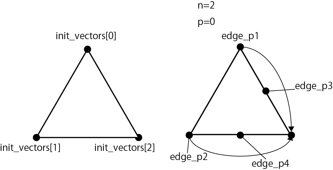
Figure 3.8: Triangle division process flow 1, calculation of edges_p1 to p4
Figure 3.8 shows the following code.
Listing 3.8: Calculation of edge_p1 to p4
for (int p = 0; p < n; p++)
{
  // edge index 1
  float4 edge_p1 = qslerp(init_vectors[i],
    init_vectors[i + 2], (float)p / n);
  float4 edge_p2 = qslerp(init_vectors[i + 1],
    init_vectors[i + 2], (float)p / n);
  float4 edge_p3 = qslerp(init_vectors[i],
    init_vectors[i + 2], (float)(p + 1) / n);
  float4 edge_p4 = qslerp(init_vectors[i + 1],
    init_vectors[i + 2], (float)(p + 1) / n);
The coordinates of edge_p1 to edge_p4 are obtained from the three points in the init_vectors array. When p = 0, p / n = 0/2 = 0 and edge_p1 = init_vectors [0], edge_p2 = init_vectors [1]. edge_p3 and edge_p4 are between init_vectors [0] and init_vectors [2] and between init_vectors [1] and init_vectors [2] at (p + 1) / n = (0 + 1) / 2 = 0.5, respectively. .. It is a flow that mainly divides the right side of the triangle.
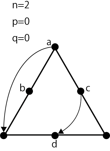
Figure 3.9: Triangle division process flow 2, abcd calculation
Figure 3.9 shows the following code.
Listing 3.9: Calculation of coordinates a, b, c, d
for (int q = 0; q < (n - p); q++)
{
  // edge index 2
  float4 a = qslerp(edge_p1, edge_p2, (float)q / (n - p));
  float4 b = qslerp(edge_p1, edge_p2, (float)(q + 1) / (n - p));
  float4 c, d;

  if(distance(edge_p3, edge_p4) < 0.00001)
  {
    c = edge_p3;
    d = edge_p3;
  }
  else {
    c = qslerp(edge_p3, edge_p4, (float)q / (n - p - 1));
    d = qslerp(edge_p3, edge_p4, (float)(q + 1) / (n - p - 1));
  }
The coordinates of the vertex abcd are calculated using edge_p1 to p4 obtained in the previous section. It is a flow that mainly divides the left side of the triangle. Depending on the conditions, the coordinates of edge_p3 and edge_p4 will be the same. This happens when the right side of the triangle reaches a stage where it can no longer be divided. In that case, both c and d take the lower right coordinates of the triangle.
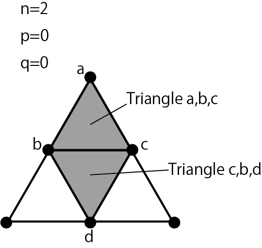
Figure 3.10: Flow of triangle division processing 3, output triangle abc, triangle cbd
Figure 3.10 shows the following code.
Listing 3.10: Output the triangle connecting the coordinates a, b, c & the triangle connecting the coordinates c, b, d
output1.pos = UnityObjectToClipPos(input[0].pos + mul(_TRS, a));
output2.pos = UnityObjectToClipPos(input[0].pos + mul(_TRS, b));
output3.pos = UnityObjectToClipPos(input[0].pos + mul(_TRS, c));

outStream.Append(output1);
outStream.Append(output2);
outStream.Append(output3);
outStream.RestartStrip();

if (q < (n - p - 1))
{
  output1.pos = UnityObjectToClipPos(input[0].pos + mul(_TRS, c));
  output2.pos = UnityObjectToClipPos(input[0].pos + mul(_TRS, b));
  output3.pos = UnityObjectToClipPos(input[0].pos + mul(_TRS, d));
  outStream.Append(output1);
  outStream.Append(output2);
  outStream.Append(output3);
  outStream.RestartStrip();
}
Convert the calculated coordinates of a, b, c, d to the coordinates for the screen by multiplying by UnityObjectToClipPos or the world coordinate transformation matrix. After that, outStream.Append and outStream.RestartStrip output two triangles connecting a, b, c and c, b, d.
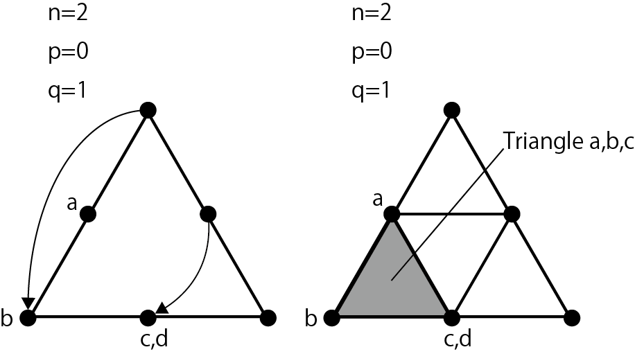
Figure 3.11: Flow of triangle division processing 4, when q = 1
When q = 1, a is 1/2 = 0.5, so it is in the middle of edge_p1 and edge_p2, and b is 1/1 = 1, so it is in the position of edge_p2. Since c is 1/1 = 1, edge_p4 is calculated, and d is calculated for the time being, but it is not used because it does not fall under the condition of if (q <(n --p -1)). Outputs a triangle connecting a, b, and c.
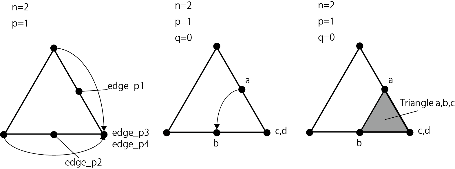
Figure 3.12: Triangle division process flow 5, when p = 1
This is the flow when the for statement of q ends and p = 1. Since p / n = 1/2 = 0.5, edge_p1 is between init_vectors [0] and init_vectors [2], and edge_p2 is between init_vectors [1] and init_vectors [2]. The subsequent coordinate calculation of a, b, c, d and the output of the triangles a, b, c are the same as the above processing. You have now divided one triangle into four. All the triangles of the octahedron are processed up to the above.
In addition to this, we have prepared three samples that cannot be introduced due to space limitations, so please take a look if you are interested.
図3.13: SampleOctahedronSphereMultiVertexInstancingシーン
In this chapter, we explained the application of Geometry Shader for line representation. Geometry Shader usually divides polygons and creates plate polygons of particles, but you should also try to find interesting expressions by using the property of dynamically increasing the number of vertices.